20-foot Energy Storage
Container Heptafluoropropane
Fire Suppression Solution
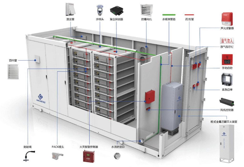
20-foot standard energy storage container (internal dimensions approximately 5.8m × 2.35m × 2.39m, volume about 32.5m³), equipped with lithium iron phosphate battery clusters, PCS, BMS, and supporting electrical equipment. The primary risks include thermal runaway of batteries releasing flammable gases (H₂, CO), electrical fires, and reignition of lithium batteries. An integrated fire protection system comprising “flammable gas early warning + composite detection and alarm + heptafluoropropane total flooding fire suppression + coordinated risk control” is required.
Design Basis
What is the design basis of this project
Five different types of design specifications
GB 50370-2025
《Design Specification for Gas Fire Extinguishing Systems》
GB/T 46261-2025
《General Technical Requirements for Fire Monitoring and Early Warning System of Electrochemical Energy Storage Power Station》
T/CEC 373-2020
《Technical Specification for Prefabricated Cabin Energy Storage Power Station》
GB 18614-2012
《Heptafluoropropane fire extinguishing agent》
GB 25972-2010
《Gas fire extinguishing system and components》
Fire risk analysis
What are the fire risk analyses for this project
Specific analysis items for four different risks
Risk of combustible gas leakage
During the initial stage of battery thermal runaway, flammable gases such as H ₂ (explosive limit 4% -75%) and CO are released, which can easily accumulate at the top of the box and cause explosions when encountering electric sparks. Early graded warning is required.
Electrical fire risk
PCS、 Short circuits/overloads in distribution cabinets and circuits can cause open flames, which develop rapidly and spread rapidly.
Risk of thermal runaway in lithium batteries
Single battery failure triggers chain thermal runaway, releasing high-temperature gas and electrolyte, prone to reignition, requiring rapid fire extinguishing and continuous suppression of reignition (≥ 30 minutes)
Risk of confined space
Total flooding systems protect the entire BESS container, including cable trays, HVAC systems, and auxiliary equipment.
Overall System Design
The overall system design of this project
Adopting a four level architecture of “detection layer → control layer → fire extinguishing layer → linkage layer”
Detection layer
Combustible gas detector (H ₂+CO), composite detector (smoke detector+temperature detector+CO), battery cluster built-in detector
control layer
Gas fire extinguishing controller, combustible gas alarm host, BMS linkage interface
Fire extinguishing layer
Cabinet style heptafluoropropane fire extinguishing device, pipeline network, dedicated nozzle
Linkage layer
Emergency start stop button, sound and light alarm, air release indicator light, pressure relief port, power cut-off device.
Division of protective zones
The 20 foot container is divided into one independent protection zone (with a volume of 32.5m ³<1600m ³, meeting the requirements of prefabricated fire extinguishing device protection zone). The fire resistance limit of the enclosure structure in the protection zone is ≥ 0.5h, the ceiling is ≥ 0.25h, and the allowable pressure is ≥ 1200Pa. One pressure relief port (with a net height of more than 2/3 and an area of ≥ 0.15 ㎡) is set at the top, which is automatically opened when closed or sprayed during normal operation.
System Design
Design of Gas Detection and Alarm System (Early Warning Core)
Detection medium and technical parameters
Detecting gases
Hydrogen gas (H ₂)+carbon monoxide (CO) (combustible gas characteristic of battery thermal runaway);
Level 1 alert
H ₂ ≥ 80ppm, CO ≥ 50ppm (linked power reduction/cut-off charging)
Level 2 alarm
H ₂ ≥ 500ppm, CO ≥ 200ppm (linked sound and light alarm+start fire extinguishing delay)
detector type
Explosion proof composite combustible gas detector (IP65, explosion-proof grade Ex d IIC T4), supports RS485 communication, response time ≤ 30s.
Detector layout (full coverage without dead corners)
Top area (flammable gas accumulation zone)
Uniformly arrange detectors on the top of the container
Battery cluster area
Install detectors to closely monitor the gas production caused by thermal runaway of batteries
Electrical compartment area
PCS、 Install detectors above the distribution cabinet to monitor electrical faults and gas production
Alarm host and linkage logic
Configure a combustible gas alarm host (wall mounted, installed on the outside of the container) to display gas concentration in real-time, store historical data, and support local sound and light alarms and remote signal uploads
Linkage logic:
Level 1 warning:
The alarm host is linked to the BMS to cut off the charging power, reduce the discharging power, turn off the air conditioning, and start the explosion-proof fan
Level 2 alarm:
The alarm host is linked to the gas fire extinguishing controller, triggering an audible and visual alarm and initiating a 30 second fire extinguishing delay (personnel evacuation within the delay can be manually stopped).
System Design
Design of heptafluoropropane fire extinguishing system
Total submergence+rapid fire extinguishing
Selection and Parameters of Fire Extinguishing Agents
| parameter item | Technical indicators/specifications |
|---|---|
| fire extinguishing agent | Heptafluoropropane (HFC-227ea), with ODP=0, no residue, non-conductive, suitable for extinguishing fires in lithium batteries and electrical equipment |
| Fire extinguishing design concentration | 9% (energy storage battery/electrical fire, GB 50370) |
| Design spraying time | ≤ 8s (rapid suppression of thermal runaway) |
| Fire extinguishing immersion time | ≥ 30 minutes (continuous suppression of reignition, meeting energy storage requirements) |
Selection and Quantity Calculation of Fire Extinguishing Devices
Type of device:
Cabinet type heptafluoropropane fire extinguishing device (prefabricated), installed at one end of the container (fire compartment), does not require complex pipe networks, and is suitable for small volume protective areas;
Quantity calculation:
The volume of the protective zone V=5.8 × 2.35 × 2.39 ≈ 32.5m ³; Density of heptafluoropropane ρ=1412kg/m ³ (20 ℃); Design dosage M=V × C × ρ/(1-C)=32.5 × 0.09 × 1412/(1-0.09).
Design layout
Pipeline network and nozzle layout
fully submerged coverage
pipeline network design
Using seamless steel pipe (DN40), the main pipeline is arranged along one side of the top of the box, and branch pipelines are connected to each nozzle. Safety valves and pressure relief valves are installed
Nozzle arrangement
Using seamless steel pipe (DN40), the main pipeline is arranged along one side of the top of the box, and branch pipelines are connected to each nozzle. Safety valves and pressure relief valves are installed
Top
evenly arrange fully submerged nozzles (spacing ≤ 3m), spray downwards, covering the upper space of the box
Battery cluster area
Special nozzles are arranged above each row of battery clusters to accurately cover the gaps between battery clusters
Electrical cabin
Install nozzles to cover PCS and distribution cabinets.
Control logic (automatic+manual+emergency stop)
Automatic control (default)
Trigger conditions:
Combustible gas level 2 alarm+composite detector (smoke and temperature) alarm (double confirmation, reducing accidental spraying);
Process:
Dual signal triggering → Sound and light alarm (inside and outside the box) → 30s delay (can be manually stopped) → Cut off the main power supply, close the ventilation port → Start the heptafluoropropane device → Spray completed within 8 seconds → Maintain concentration ≥ 30 minutes → Link BMS to monitor battery status.
System Protection
Composite detection assistance system
Double confirmation, anti false alarm
In conjunction with combustible gas detection, a composite detector (smoke detector+temperature detector+CO) is configured to achieve dual confirmation of fire:
Function: Monitor smoke, temperature (≥ 70 ℃ alarm), CO concentration, and link with combustible gas signals * * “and logic” to extinguish fires * *, avoiding accidental triggering of a single detector
Recommended Products
System linkage and security protection
List of linkage equipment
| Device Name | function |
| audible and visual alarm | Alarm Alert |
| Deflation Indicator Light | Spray warning |
| Emergency start stop button | Manual start/stop |
| Pressure relief port | Spray and release pressure |
| Power cut-off device | Fire power outage |
| Explosion-proof fan | Ventilation during warning |
Safety protection requirements
1. Post warning signs at the entrance of the protective zone (“Gas fire extinguishing, no entry”);
2. The system power supply adopts DC24V dual circuit power supply, and the standby power supply has a battery life of ≥ 24 hours;
3. Annual inspection of fire extinguishing devices and quarterly calibration of detectors to ensure system reliability;
4. The box is equipped with a grounding device, with a grounding resistance of ≤ 4 Ω and anti-static accumulation.
solution
Solution Advantages
What are the solutions
Early warning
Combustible gas detection (H ₂+CO) provides a 5-10 minute advance warning for thermal runaway, which is earlier than traditional smoke/temperature sensors and allows for disposal time;
Quick fire extinguishing
Within 8 seconds, heptafluoropropane is sprayed and fully submerged to quickly extinguish open flames and suppress the spread of thermal runaway
Anti reignition
30 minutes of immersion time, continuously maintaining the extinguishing concentration, effectively preventing lithium battery reignition
Safety and environmental protection
The fire extinguishing agent has no residue, is non-conductive ODP=0, Protect equipment and be environmentally friendly
Double confirmation to prevent accidental spraying
Combustible gas+composite detection dual signal linkage, reducing the risk of accidental triggering
Implement acceptance inspection
Key points of implementation and acceptance
What are the standards for implementing acceptance
1. Before construction, verify the equipment qualifications (3C certification, explosion-proof certification) to ensure compliance with national standards;
2. After the installation of the pipeline network, conduct a water pressure test (1.5 times the working pressure, hold for 30 minutes without leakage);
3. The detector should be installed in a precise position to avoid obstruction, and fixed after calibration;
4. System debugging: Simulate combustible gas leakage and fire signals, test whether the linkage logic is normal;
5. Acceptance shall be based on GB 50370 and GB/T 46261, and a fire detection report shall be issued to ensure compliance.
Protect Your BESS Investment
Get a customized fire protection proposal for your battery
energy storage project. Free engineering consultation
included.